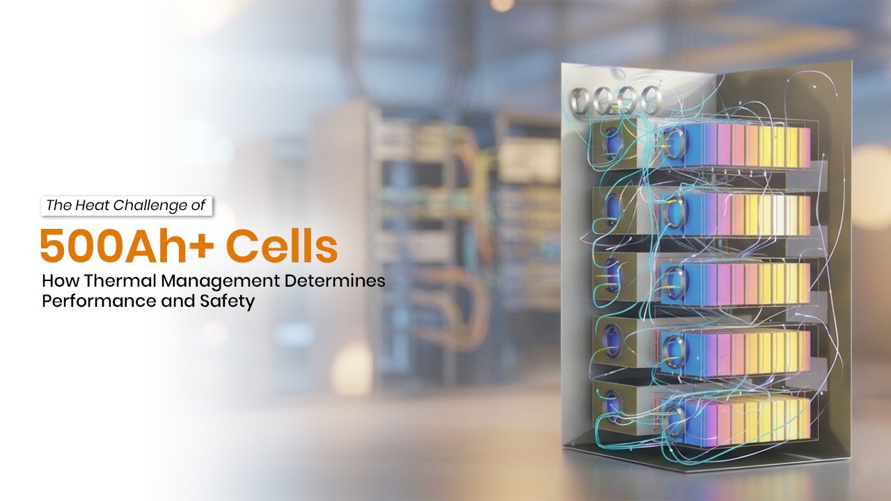
The Big-Cell Revolution and Its Thermal Price Tag
The battery energy storage industry is in the midst of a profound format shift. Over the past five years, the dominant cell capacity in grid-scale BESS has climbed from 280Ah to 314Ah — and now leading Chinese manufacturers are aggressively scaling beyond 500Ah. CATL is commercializing its 587Ah cell, EVE Energy is pushing the 628Ah “Mr. Big,” REPT BATTERO markets a 587Ah Wending® cell at 430 Wh/L, Sunwoda Energy launched a 684Ah format, and HiTHIUM has crossed the 1,000Ah barrier with its 1,175Ah ∞Cell. A single 560–587Ah cell now stores roughly twice the energy of a 280Ah predecessor — meaning far fewer cells are needed to build a 5–6 MWh container.

The Propagation Problem in Dense Container Configurations
Modern 5–6 MWh containers pack hundreds of large-format cells in tight configurations to maximize volumetric energy density. In a Cell-to-Pack architecture, cells sit directly in the container frame without intermediate module casings — improving density by 15–20% but reducing the structural thermal barriers between cells. Under thermal runaway propagation studies, three patterns have been identified: ordered, disordered, and synchronous propagation — with the synchronous pattern generating the largest energy release and most severe structural damage.

This is why modern BESS container design must integrate not just active cooling, but also passive containment architecture: fire-resistant barriers, venting channels to direct gases away from adjacent cells, and gap-filler materials that can serve as both thermal interface material and fire barrier simultaneously.
Overheating: A Problem that every Battery Cell must address
From CATL’s mass production and delivery of 587Ah batteries to EVE Energy’s batch application of 628Ah batteries, 500Ah+ high-capacity cells are sweeping the energy storage market with unstoppable momentum. Containerized systems of 6.25MWh, 6.9MWh, and even 12.5MWh have emerged one after another, doubling the energy density of energy storage systems within two years.
As the industry consensus has reached the 500Ah+ era for energy storage cells, an unavoidable problem is emerging – heat dissipation. Larger cells generate three times the heat of their predecessors, making air cooling ineffective and liquid cooling overloaded. Thermal management is becoming the biggest bottleneck restricting the widespread adoption of larger cells.

The previous generation of 280Ah/314Ah cells had a heat output of about 10~15W under the standard 0.5P operating condition. As the capacity has increased to 587Ah or even 600Ah and above, the heat output of the cells under the same 0.5P operating condition has reached 30~40W, which is an amazing increase.
What’s more troublesome is that as the cell capacity increases, its size also increases, with a 10mm increase in height and a 110mm increase in thickness, thus lengthening the heat conduction path. Heat generated in the core area of the cell must pass through thicker electrodes and a larger casing to reach the outer surface and be carried away by the cooling system. The larger the cell, the longer this heat transfer path becomes.

The heating power has increased by 3 times, and the heat transfer path has become longer. This is a very tricky problem encountered by 500Ah+ large-capacity cells in energy storage applications. If not handled properly, it will seriously affect the temperature rise and temperature difference of the cells, and thus significantly shorten the cycle life of the energy storage system.
No matter how long the cycle life of the battery cells is, without a good thermal management solution, the energy storage system will be short-lived.
Solution: Neither Air Cooling nor Bottom Liquid Cooling works.
Air cooling: Inherently deficient, accelerating its exit from the era of large battery cells.
Air cooling, as the name suggests, uses air as the cooling medium. Cool air circulated through an air conditioning system is blown across the surface of the battery cells, carrying away heat. This solution was widely adopted when energy storage systems were still small-scale and battery cell capacities were below 200Ah, due to its advantages of low cost, simple structure, and easy maintenance. In the early stages of promoting 280Ah battery cells, air cooling systems were the most common, but their shortcomings were also quite obvious.
The convective heat transfer coefficient of air is only 25~100 W/(m²·K), while that of liquids can reach 500~1500 W/(m²·K). The thermal conductivity of liquids is about 25 times that of air, and their specific heat capacity is also much higher. For the same temperature difference, liquid cooling removes far more heat than air cooling.

Therefore, with the widespread adoption of 314Ah battery cells, liquid cooling has replaced air cooling as the mainstream method. Air cooling is still only used in long-term energy storage applications such as 4-hour or 8-hour backup power.
Bottom liquid cooling: It has some effect, but its functionality is severely insufficient.
The mainstream form of liquid cooling solutions involves placing a liquid cooling plate at the bottom of the battery cell, allowing the coolant to carry away heat from the bottom. This solution played a crucial role in the 280Ah/314Ah era, but it has two fundamental drawbacks when dealing with larger battery cells:
- The closer the heat source is to the top of the battery cell, the more heat needs to be conducted downwards to be carried away. The taller the battery cell, the longer this path, and the more heat accumulates along the way. Because the heat dissipation power of a 500Ah+ battery cell is much greater than that of a 280Ah/314Ah cell, the problem of heat conduction and accumulation is very serious, resulting in a very large temperature difference between the top and bottom.
- Bottom liquid cooling has a heat exchange area that is only the bottom area of the battery cell—and for large battery cells, this is only a small fraction of the total heat dissipation area. Insufficient heat exchange area directly limits the maximum heat dissipation capacity.

Using 587Ah cells in a group, a bottom liquid cooling scheme was modeled and simulated for verification. With the coolant temperature controlled at 20℃ and operating at 0.5P, the highest surface temperature of the cell reached 35℃, and the temperature difference between the top and bottom of the cell reached an alarming 13.2℃. The aging rates of the upper and lower halves of the cell differed greatly, with the upper half aging more than 25% faster than the bottom half, which is completely unacceptable.
Breaking the deadlock: Finding new solutions to the heat dissipation problem
Route 1: Front liquid cooling – extremely high efficiency
Front liquid cooling, as the name suggests, involves moving the liquid cooling plate from the bottom of the cell to the front of the cell (i.e., the wide side of the cell), so that it directly contacts the two largest heat dissipation surfaces of the cell.
Front-side liquid cooling solves two fundamental problems of bottom-side liquid cooling: the heat exchange area is expanded from the bottom to the front, which is a full 8 times larger, and the thermal resistance can be reduced to 1/8 of the original; the heat transfer path is shortened from 215mm to half of the cell thickness, i.e., 37mm, which is 83% shorter.

These two improvements can directly lead to an exponential improvement in temperature rise and temperature difference, achieving amazing results.
However, this comes at a cost. Bottom liquid cooling only requires a single complete cold plate, which is easy to manufacture and has low cost. On the other hand, front liquid cooling requires more than a dozen independent cold plates, plus supporting pipes, thermal adhesive, and structural components, making the system extremely complex and costly.
This is an obstacle to the widespread adoption of front-side liquid cooling.
Route 2: Side liquid cooling – Solving engineering challenges
Side liquid cooling involves moving the liquid cooling plate from the bottom of the cell to the side of the cell (i.e., the narrow side of the cell), where the coolant carries away heat from both sides of the cell.
The heat exchange area of the side liquid cooling is 50% larger than that of the bottom liquid cooling, and the heat transfer path is shortened from 215mm to half the width of the cell, i.e., 142mm, which is 34% shorter. These two changes can significantly improve the heat dissipation conditions of the cell.

Modeling and simulation were performed using 587Ah battery cells in a pack, based on a side liquid cooling solution. The coolant temperature was controlled at 20℃. Under 0.5P conditions, the highest surface temperature of the battery cell was 28℃, the temperature difference from the center of the cell to the side was 6.8℃, and the maximum temperature difference among all cells in the pack was 1.4℃.
Compared to bottom liquid cooling solutions, the cell temperature rise, intra cell temperature difference, and inter-cell temperature difference are all significantly improved and within acceptable ranges. Compared to front liquid cooling solutions, the number of cold plates, structural complexity, and cost are greatly reduced.

Route 3: Immersion Liquid Cooling – Large-scale deployment is still a long way off.
Immersion liquid cooling directly submerges the battery cells in insulating coolant, allowing heat to be carried away directly through coolant circulation. This represents the pinnacle of energy storage thermal management.

The temperature rise of the immersion liquid-cooled battery cell can be controlled within 5℃, the temperature difference between cells is ≤2℃, and there is basically no temperature difference inside the cell. The coolant completely isolates the cell from the air, naturally forming a fire suppression system. Its ability to prevent the spread of thermal runaway far exceeds that of traditional solutions, achieving “zero spread” of thermal runaway.
However, immersion liquid cooling faces three major engineering challenges:
① The cost of insulating coolant (fluorinated liquid/modified silicone oil) is high. Fluorinated liquid is much more expensive than ethylene glycol aqueous solution, and the amount used is particularly large, resulting in high costs;
② The sealing requirements are extremely stringent, making it difficult to achieve a leak-free seal for ten years, and leak handling is extremely complex;
③ Corrosion and compatibility issues. Battery cells, aluminum bars, copper busbars, and other structural and electrical components are immersed in coolant for a long time, posing a risk of chemical reactions.

Currently, immersion liquid cooling is still in the demonstration project stage, and its maturity is far from sufficient. It will take at least 5 more years before it can be applied on a large scale.
The India Dimension: Ambient Temperature as a BESS Design Variable
Thermal management for 500Ah+ BESS is a global challenge, but it is an existential design parameter for India. Industrial zones across Rajasthan, Gujarat, Maharashtra, and Uttar Pradesh regularly see ambient temperatures approaching 45–50°C. This single factor changes the engineering calculus entirely.
Consider the lifecycle implications quantified in peer analysis:
- Sustained operation at 30°C: ~20% shorter battery lifetime versus 20°C baseline
- Sustained operation at 40°C: ~40% lifetime reduction
- Sustained operation at 45°C: usable battery life may drop by half

For Indian BESS developers, this means that a system designed to the standard global specification — optimized for a 25–35°C ambient — will dramatically underperform and underdeliver on contracted cycle life when deployed without climate-specific thermal engineering. As industry observers have noted, globally designed systems cannot simply be deployed in India and expected to achieve optimal outcomes. Liquid cooling systems engineered for Indian conditions can maintain cell temperatures within ±3°C even at 45°C+ ambient, while air-cooled systems at the same site degrade with uneven cell temperatures, reduced round-trip efficiency, and accelerated capacity loss.

The India localization challenge for 500Ah+ cells specifically includes:
- Module redesign: Larger cells require re-engineered busbar layouts, thermal interface materials (TIMs), and mechanical support structures designed for >1000A discharge currents
- CFD validation: Larger cell surface areas complicate heat uniformity and coolant distribution, requiring computational fluid dynamics validation before deployment
- Advanced TIMs: Higher performance thermal interface materials between cells and cold plates that remain stable at high ambient temperatures
- Serviceability SOPs: Field replacement of heavy 500Ah+ cells requires special tools, trained technicians, and robust safety procedures adapted for high-heat environments
Design Principles for 500Ah+ Thermal Management
Translating research findings into actionable design guidance for 500Ah+ BESS:
Cell-Level Design Considerations
- Multi-tab architecture: Distributing current collection across more tabs shortens the current path through the electrode, reducing internal heat generation per unit area
- SOC management: Operating 500Ah+ cells at 80–90% maximum SOC rather than 100% SOC significantly extends thermal runaway propagation time between adjacent cells — from 87s to 307s at the module level
- Electrode uniformity tolerance: At 500Ah+ formats, coating non-uniformity and defect propagation are amplified; tighter acceptance criteria during cell incoming inspection are essential

Module and Rack-Level Design
- Size cooling systems for worst-case C-rate at peak ambient temperature — not rated averages
- Use zoned cooling loops that allow different thermal zones in a rack to receive different coolant flow rates
- Incorporate thermal barriers between cell clusters to limit inter-cluster propagation while maintaining intra-cluster cooling
- Place temperature sensors at both the top and bottom of each cell, given documented vertical temperature gradients in large-format LIBs

System and Container Level
- Design vent channels to direct gas away from adjacent modules in thermal runaway scenarios
- Apply anti-flammable materials at module and rack levels to limit fire propagation
- Validate UL 9540A compliance at rack level — not just cell level — since larger cells increase inter-module propagation risk
- For India, specify chillers rated for sustained 45°C+ ambient operation rather than standard 35°C-rated equipment

Conclusion
Mass production of 500Ah+ high-capacity battery cells is a foregone conclusion, but the industry has run into the physical problem of heat generation. How to solve this problem will have a significant impact on the future development of the industry. Bottom liquid cooling is clearly not the right option, but due to inertia, most integrators still follow this path, which will lead to major problems for the product in the market.
As far as I know, this problem has already occurred. When heat dissipation becomes a key factor affecting the temperature rise, energy efficiency, and cycle life of energy storage systems, the ability to achieve low-cost, high-reliability, high-safety, and highly adaptable engineering solutions becomes the deciding factor in the competition among integrators. We, on the other hand, have been laying the groundwork for this sector for a long time and have solved the challenges of industrialization and scaling.
The solutions exist: hybrid PCM + cold plate architectures, multi-zone liquid cooling with CFD-validated flow distribution, adaptive BMS with predictive thermal models, and cell-level multi-point sensing. The engineering community’s challenge for 2026–2028 is to prove that these solutions can be deployed reliably, cost-effectively, and at the scale required — in the climates where energy storage is growing fastest.
No responses yet