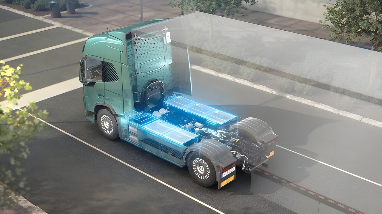
India’s electric-vehicle testing regime was built almost entirely around low-voltage two- and three-wheeler packs, and while AIS-156 and AIS-038 (Rev 2) have been substantially tightened since the 2022 fire wave, the testing infrastructure, standard maturity, and validation depth for high-voltage packs in e-buses (M3) and e-trucks (N2/N3) lag years behind what the vehicles’ voltage class, duty cycle, and duration of exposure actually demand.

This is the “high-voltage battery pack testing gap” nobody talks about: a scaling mismatch between how thoroughly a 3–5 kWh two-wheeler pack gets tested versus how a 300–600 kWh bus or truck pack — often 400V to over 800V — gets validated before it goes into daily 200-plus km duty cycles carrying 50+ passengers or multi-tonne freight.
Structural Dynamics and Mechanical Integration Discrepancies
The physical scaling of battery packs from passenger cars to commercial vehicles introduces complex structural and mechanical testing challenges. Because state-of-the-art commercial lithium-ion cells yield gravimetric energy densities typically bounded between 0.015 kWh/kg at the pack system level and ~0.3 kWh/kg (300 Wh/kg) at the cell level, achieving heavy-duty operational range targets requires packs weighing between 500 kg for modular bus units up to more than 3,400 kg (7,500 lbs) for full long-haul truck installations.

The structural integration of these massive packs differs fundamentally across vehicle segments. Passenger electric vehicles typically incorporate the battery pack into the floorpan, creating a planar structure that benefits from continuous chassis support, lowers the vehicles center of gravity, and distributes torsional loads evenly across multiple underbody attachment points. In contrast, heavy-duty electric trucks mount their battery packs internally or externally along rigid ladder frame rails. Restricted by a minimal number of mounting locations, these truck packs are directly exposed to the intense chassis flexing, dynamic twisting, and high-amplitude longitudinal vibration characteristic of long-haul commercial highway and off-road driving cycles.
Commercial electric buses present an entirely different structural challenge, as spatial constraints frequently require packs to be mounted either within the rear overhang or on the vehicle roof. Roof-mounted bus battery systems must be designed as self-supporting structural enclosures that transfer their static and dynamic mass directly into the vertical side pillars of the body shell rather than relying on floorpan support. This design significantly elevates the vehicles center of mass, subjecting the pack housing and its mounting brackets to intense lateral dynamic sway, severe bending moments, and complex roof-deformation stresses during aggressive cornering or collision maneuvers.

The Electrical Scale Shift and Megawatt Charging System (MCS) Stresses
To mitigate payload penalties, commercial vehicle OEMs are shifting from legacy 400V/800V architectures to operating platforms exceeding 1,000V. Raising platform voltage allows high power transfer while minimizing copper wire gauge mass; however, elevated direct-current voltages accelerate dielectric degradation, strain insulation barriers, and increase the risk of high-voltage isolation loss. Environmental factors such as moisture ingress, high humidity, condensation, and road dust contamination drastically degrade creepage and clearance distances, inviting catastrophic arcing within dense pack enclosures.
Concurrently, heavy-duty fleet economics demand minimal vehicle downtime during mandatory driver rest breaks, driving the industry away from standard Combined Charging System (CCS) interfaces toward the Megawatt Charging System (MCS).

The Insulation and Dielectric Stress Problem
Automotive HV insulation testing has historically been built around the assumption that verification voltages need to be roughly double the operating voltage plus a margin. As truck systems push toward and beyond 1.5 kV, testing voltages of 4 kV or more become necessary just to validate insulation integrity, and researchers now expect kilovolt-class testing to become routine within the next decade as truck and construction-vehicle DC links approach 870V and beyond. Some OEMs already require drivetrain components rated for 800V operation to withstand test voltages up to 4,000V DC and 2,000V AC — five times the nominal operating voltage — specifically because reliability margins at this scale cannot be verified any other way.

Wide-band-gap semiconductors (SiC, GaN) used in truck power electronics compound this: their fast-switching, ultra-short rise times accelerate insulation deterioration through partial discharge effects that conventional automotive test protocols weren’t designed to detect. This means many test benches and hipot/insulation-resistance instruments calibrated for 400–600V EV platforms are functionally inadequate for 800–1,200V truck packs, cables, and inverters — a hardware gap layered on top of a standards gap.
Comparing the Testing Landscape Across Vehicle Classes

Laboratory Infrastructure Shortfalls and Thermal Propagation Containment
The physical requirements for testing 500+ kWh commercial battery packs present severe capital and safety barriers for testing facilities. Standard automotive test laboratories designed for 80 kWh car packs are structurally and electrically unequipped to handle commercial systems weighing up to 3,500 kg. Building an accredited commercial battery testing laboratory compliant with ISO 17025 demands capital expenditures exceeding $10 million and commissioning lead times extending up to 24 months.
The primary physical challenge lies in thermal runaway propagation (TRP) testing under severe abuse conditions (e.g., nail penetration, overcharging, localized external heating, or mechanical crush). The thermal energy stored within a fully charged 500 kWh pack is massive (~1.8 Gigajoules). If thermal runaway cascades from a single cell across a large-format module, the resulting exothermic chain reaction generates extreme hazards:

- Directional Jet Fires: Vented gases, vaporized organic carbonates, and incandescent active materials are ejected at high velocities through pressure relief vents, forming sustained directional jet flames.
- Toxic and Flammable Gas Volumes: Off-gassing releases thousands of cubic meters of flammable hydrogen H2, carbon monoxide CO, methane CH4, and highly corrosive hydrofluoric acid HF aerosols.
- Re-ignition and Explosive Deflagration: Even after visible open flames are suppressed, lingering hot particles and thermal inertia within massive commercial pack structures can cause delayed re-ignition hours after the primary event.

Standard laboratory environmental chambers lack the blast containment walls, explosion-relief venting, thermal insulation, and toxic scrubber capacities required to manage an unmitigated TRP failure of a 500+ kWh battery system. Furthermore, performing high-power electrical cycling tests requires specialized bi-directional DC power supplies capable of sourcing and sinking up to 3.84 MW. Operating these high-power test benches without straining local municipal power grids requires dedicated, on-site stationary battery energy storage systems (BESS) to buffer high-power load spikes during rapid continuous charge-discharge cycling.

Advanced Hardware-in-the-Loop (HIL) and End-of-Line (EOL) Validation Technologies
Because physical destructive testing of multi-pack heavy-duty batteries is expensive, hazardous, and difficult to reproduce, the industry relies increasingly on Hardware-in-the-Loop (HIL) and Power Hardware-in-the-Loop (PHIL) simulation platforms. Commercial e-trucks and e-buses rarely use a single centralized BMS; instead, they deploy distributed master-slave topologies across multiple physical packs mounted in parallel or series strings. The master BMS coordinates high-level pack safety, contactor sequencing, state-of-charge (SOC) estimation, and thermal routing, while multiple slave module controllers manage localized cell monitoring and balancing.
Validating these complex distributed control architectures requires high-channel-count, FPGA-based HIL test rigs capable of emulating hundreds of individual battery cells deterministically. Key HIL and PHIL validation workflows include:

- Cell Emulation and Fault Insertion: FPGA platforms simulate individual cell voltage behavior with millivolt accuracy across wide dynamic ranges, allowing safety engineers to inject precise fault conditions—such as a single shorted cell, open-circuit voltage sensing lines, or drifted thermistor readings—to test BMS safety triggers without risking physical pack destruction.
- Virtual Sensors for Electrochemical State Detection: Traditional BMS software relies on conservative, static lookup tables to restrict charging current and prevent damaging side reactions. Modern BMS software integrates real-time electrochemical physics metamodels (virtual sensors). These algorithms track the internal anodic overpotential in real time, calculating a continuous Lithium Plating Risk Indicator (LPRI). Integrating LPRI feedback into the charging loop allows the system to maximize fast-charging power dynamically without crossing into plating regimes.
In addition to software validation, completed commercial packs must undergo high-resolution End-of-Line (EOL) manufacturing diagnostics to verify assembly integrity prior to vehicle integration.

Strategic Industry Outlook and Implementation Roadmap
Closing the high-voltage battery pack testing gap requires a coordinated realignment across automotive OEMs, Tier-1 suppliers, regulatory bodies, and test equipment providers. Relying on passenger-car test standards for heavy-duty commercial powertrains creates significant commercial, regulatory, and safety risks.
To build a resilient validation framework for e-buses and e-trucks, the industry must execute against four strategic imperatives:
- Regulatory Modernization: Standards organizations must revise regulations such as UN ECE R100, UL 2580, and SAE standards to introduce distinct testing tracks specifically tailored for heavy-duty commercial applications. Mechanical vibration profiles must incorporate multi-axis frame twisting for chassis-mounted truck packs and lateral sway resonant profiles for roof-mounted bus enclosures.
- Megawatt Laboratory Infrastructure Expansion: Testing facilities must invest in specialized blast-rated containment structures equipped with high-capacity scrubbers, active liquid-cooling loops for 3,000 A MCS charging, and bi-directional DC power platforms reaching 3.84 MW. Utilizing localized BESS installations will prevent high-power test benches from destabilizing local electrical grids.

- Deployment of Physics-Based BMS HIL Testing: System integrators should adopt FPGA-driven BMS HIL and PHIL test benches capable of emulating master-slave architectures across diverse operating envelopes. Integrating real-time electrochemical models into BMS control units will enable safe, adaptive fast-charging regimes while eliminating the cell degradation feedback loops that lead to premature pack retirement.

No Responses