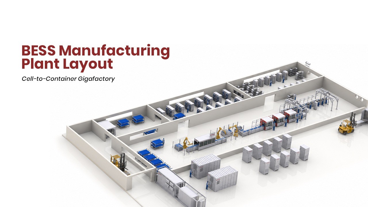
As the global energy storage industry accelerates, the way we design a BESS (Battery Energy Storage System) manufacturing plant is becoming just as important as the technology inside the containers. A well-engineered plant layout is the backbone of quality, safety, throughput, and traceability — and the layout shared here is a great example of how a modern cell-to-container BESS facility should flow.

Let’s walk through the logic of this design, zone by zone.
1. Macro Layout Architecture and Spatial Logistics Strategy
The structural layout of a giga-scale BESS manufacturing plant utilizes a rectangular, unidirectional spatial arrangement engineered to eliminate material cross-docking, minimize internal transit distances, and prevent intra-facility backtracking. The plant footprint is divided into specialized operational sectors: raw material and chassis intake lanes located on the far left, kinetic buffer channels situated in the mid-left area, primary module and container assembly tracks spanning the central core, quality testing and rework stations positioned on the mid-right, and final packing and dispatch bays established on the far right.
The unidirectional flow establishes a logical progression of material movement. Raw cells, structural frames, electrical components, and bare steel container chassis enter through dedicated receiving bays. These materials move into dynamic storage buffers that feed the primary assembly lines. Completed battery packs and container sub-assemblies then advance to high-voltage testing grids before proceeding to final packaging and logistics dispatch.

2. Intake Logistics and Dynamic Buffer Management
Operational flow begins with the physical separation of incoming shipments at the far-left receiving terminal. The plant layout segregates material intake into two distinct zones: the upper Raw Material Receiving Zone and the lower Container Unloading Zone. Isolating heavy steel structural chassis handling from sensitive chemical and electrical component receiving prevents physical contamination and mitigates internal traffic congestion. Incoming lithium-ion cells—whether in prismatic, cylindrical, or pouch form factors—are unpalletized and routed through automated electrical screening. Concurrently, bare 20-foot and 40-foot ISO intermodal structural containers are unloaded via overhead gantry cranes into their designated intake bay.
To maintain continuous assembly operations without propagating line stoppages, the facility integrates a central buffer zone divided into three distinct operational lanes. The Empty Container Buffer Zone holds prepared steel enclosures ready for line entry. The Product Buffer Zone stores finished battery modules and complete packs originating from the automated assembly line. The Container Material Buffer Zone stages heavy auxiliary systems, such as Power Conversion System (PCS) inverters, liquid-cooling HVAC chillers, main busbar trunks, and aerosol fire suppression tanks.

These parallel buffering channels mitigate velocity mismatches across different manufacturing phases. Automated cell-to-pack assembly lines operate at high speeds, generating between 12 and 24 pieces per minute (PPM). In contrast, multi-megawatt container mechanical and electrical integration requires a longer takt time per finished enclosure. Intermediate storage lanes absorb fluctuations in production speed, preventing upstream bottlenecks and maintaining continuous line operation.
Material movement between storage buffers and assembly lanes is managed by Automated Guided Vehicles (AGVs) and specialized overhead cranes. Heavy-load Smart AGV conveyor systems transport structural enclosures along the container assembly track, while overhead XYZ gantry lifters move finished battery packs directly from the Product Buffer Zone into container rack structures. This approach reduces manual material handling, eliminates forklift hazards in assembly corridors, and prevents mechanical stress on battery packs during positioning.
3. High-Speed Automated Module and Pack Assembly Engineering
The central core of the upper manufacturing floor houses the Automatic Module Pack Assembly Line. Designed for high-throughput battery pack production, this automated line spans up to 66 meters in length with footprints ranging from 40 feet to 200 feet. The conveyor operates at linear speeds of 6 to 8 meters per minute and draws between 20 kW and 250 kW of continuous utility power, depending on automation scaling and laser welding requirements.
The assembly line executes a sequential manufacturing process that transforms individual lithium-ion cells into structurally compressed, laser-welded modules and packs while maintaining high production yields above 99.5%.

The process begins at the Cell Aging Machine, where incoming cells are stabilized under controlled environmental conditions to eliminate thermal and voltage anomalies. The cells then pass through the Open-Circuit Voltage (OCV) Tester and LOCV Sorting Machine, which measures voltage and internal resistance (ACIR/DCIR) to ensure precise cell sorting prior to module formation.
Sorted cells advance to the Automatic Stacking Machine, where robotic pick-and-place units align them into rigid module configurations. The stacked cells enter the Extrusion Machine, which applies uniform structural compression before end-plates are secured. This controlled mechanical compression maintains thermal interface contact and accommodates cell expansion over extended charge-discharge cycles.

Before electrical joining, modules undergo inspection at the Polarity Detection Station, where Charge-Coupled Device (CCD) optical sensors verify cell orientation to prevent short-circuit risks. Verified modules move to the Laser Cleaning Machine, where high-energy pulsed lasers remove surface oxidation and organic contaminants from terminal posts. The modules then proceed to the Laser Welding Machine, which fuses copper or aluminum busbars to cell terminals. This non-contact welding process establishes high-conductivity electrical joints with minimal heat input, protecting internal cell chemistry from thermal damage.
Following busbar joining, completed units are evaluated by the Module End-of-Line (EOL) Tester, which measures electrical continuity, weld joint resistance, and dielectric insulation. Passed modules enter the Pack Line Integration area, where they are mounted into protective pack enclosures along with local thermal management cold-plates and Battery Management System (BMS) wiring harnesses. Finally, completed packs undergo comprehensive testing at the Pack EOL Tester, which evaluates full system functionality across voltage levels from 100V to 1650V before the units are transferred to the container integration bay.
4. Dual-Row Container-Type Energy Storage System Integration
The lower central area of the factory floor contains the Container Type Energy Storage System Assembly Line. This section features a wide, dual-row integration bay designed for heavy industrial assembly. In this bay, bare steel intermodal containers move along parallel assembly tracks, where integration teams and automated positioning systems install structural racks, cooling infrastructure, electrical systems, and safety equipment.
Container assembly begins with the installation of reinforced structural racking frames. These frames are anchored to the containers structural floor and wall members, providing seismic resistance and mechanical stability during transport and site operation. Heavy-load XYZ gantry cranes then retrieve fully validated battery packs from the Product Buffer Zone and position them into the rack matrix.

Following pack installation, liquid-cooling distribution manifolds are connected throughout the container. Modern BESS designs utilize high-precision liquid cooling systems with optimized fluid flow paths to maintain cell-to-cell temperature variations within ±2°. Maintaining precise thermal control across all cells reduces degradation rates and can extend total battery service life by up to 30%, significantly improving long-term project economics.
Integration continues with the installation of electrical infrastructure and auxiliary control systems. High-voltage DC busbar trunks connect the battery racks to central Power Conversion System (PCS) inverters and grid-interconnection step-up transformers. The integration architecture supports connection voltages ranging from 415V to 132kV, enabling compatibility with diverse commercial, industrial, and utility grid networks.
Finally, technicians install multi-layer fire safety systems, including Very Early Smoke Detection Apparatus (VESDA) aspirating units, aerosol or total-flooding gas suppression canisters, automated deflagration venting panels, and centralized BMS communications controllers. Once integration is complete, the IP55-rated weatherproof enclosure is sealed and prepared for full-system testing.
5. Quality Assurance, Grid Simulation, and Automated MES Rework
Quality verification is concentrated on the right side of the facility, divided into the Pack Testing Zone and the Pack Rework Zone.
The Pack Testing Zone includes high-power electrical testing infrastructure designed to evaluate individual modules as well as fully integrated multi-megawatt-hour containers. High-voltage testing equipment operating between 100V and 1650V conducts dielectric withstand testing, insulation resistance checks, and BMS communication verification.

For complete containerized systems, specialized testing stations perform full-cycle charge and discharge evaluations at power ratings from 2.5 MW to 5 MW. Unlike component-level testing, container-level verification evaluates complete system performance under operational loads, testing high-current DC distribution, busbar thermal stability, BMS control accuracy, and HVAC cooling efficiency.
To manage electrical loads during high-power testing, the facility utilizes a back-to-back testing topology. During container discharge testing, energy is captured and fed back into the facilitys power network or redirected to power adjacent containers undergoing charge testing. Energy recovery during testing reduces overall plant utility consumption, lowers operational costs, and minimizes localized thermal emissions within the testing bay.

If a battery module or integrated container displays telemetry anomalies or fails insulation checks during testing, it is routed to the Pack Rework Zone. This zone operates on an offline diagnostic loop linked to the plants Manufacturing Execution System (MES).
Technicians scan the components unique barcode to pull its complete production record, including initial cell OCV values, robotic stacking compression data, laser welding energy logs, and real-time testing telemetry. Defective components are isolated, safely discharged, repaired, or replaced without interrupting main line production. Following rework, units re-enter the testing protocol for full re-validation before clearance for dispatch.
6. Safety Engineering, Hazardous Material Isolation, and Regulatory Compliance
Given the high energy density present in giga-scale manufacturing facilities, fire protection and thermal hazard containment are primary layout design considerations. The plant integrates early-warning monitoring, physical isolation zones, and automated safety systems to mitigate thermal runaway risks.
Thermal runaway in lithium-ion cells typically begins with internal degradation, releasing off-gas traces minutes to hours before temperature spikes or visible combustion occur. The facility deploys continuous low-PPM off-gas monitoring systems across all module assembly tracks, storage buffers, and testing bays.

The physical layout places high-power testing and rework stations away from raw material storage and primary assembly tracks to isolate potential hazards. The testing grid is constructed with blast-resistant containment walls, fire-rated utility penetrations, and automatic deluge systems. Lower Flammable Limit (LFL) tracking systems monitor gas concentrations in real time, coordinating with emergency exhaust systems to maintain atmospheric conditions safely below explosive limits.

The plant layout and its manufactured storage systems comply with international safety, environmental, and structural standards:
- NFPA 855: Dictates installation spacing, fire protection systems, and emergency isolation protocols for stationary energy storage systems.
- UL 9540 & UL 9540A: Establishes system-level safety requirements and validates resistance to thermal runaway propagation through large-scale fire testing.
- NFPA 68 & NFPA 69: Guides deflagration venting design and active flammability control to safely manage explosion risks in enclosed structures.
- IEC 62619 & UN 38.3 / AIS 156: Regulates cell and module safety for stationary energy storage and ensures safe transport handling.
7. Operational Economics and Strategic Manufacturing Considerations
The layout design of a BESS manufacturing plant directly affects production efficiency, operational expenditure, levelized storage costs, and project bankability.

Optimizing plant layouts and deploying automated assembly processes yields quantifiable economic benefits:
- Levelized Cost of Storage (LCOS) Reduction: High-speed automated assembly lines operating at 12–24 PPM achieve production yields above 99.5%, reducing material scrap and unit manufacturing costs. Precise thermal interface application and cooling integration maintain cell-to-cell temperature variations within ±2°, extending overall system cycle life and increasing total lifetime energy throughput MWh, which directly lowers LCOS.
- Total Cost of Ownership (TCO) Optimization: Standardizing integration processes across 20-foot and 40-foot container platforms simplifies field installation. Delivering fully assembled, factory-tested containers reduces field wiring requirements, minimizes on-site commissioning errors, and shortens deployment timelines.
- Digital Traceability and Project Bankability: End-to-end MES integration creates a complete digital record for every containerized system, logging cell batch origins, OCV values, laser welding parameters, and end-of-line test results. Documented compliance with standards like UL 9540 and NFPA 855 simplifies regulatory approvals, accelerates project financing, and improves insurer confidence.

Contact Semco Infratech to discuss your EV & BESS manufacturing requirements and discover how automatic assembly solutions can enhance your production efficiency, ensure product quality, and accelerate your path to market competitiveness.
No Responses