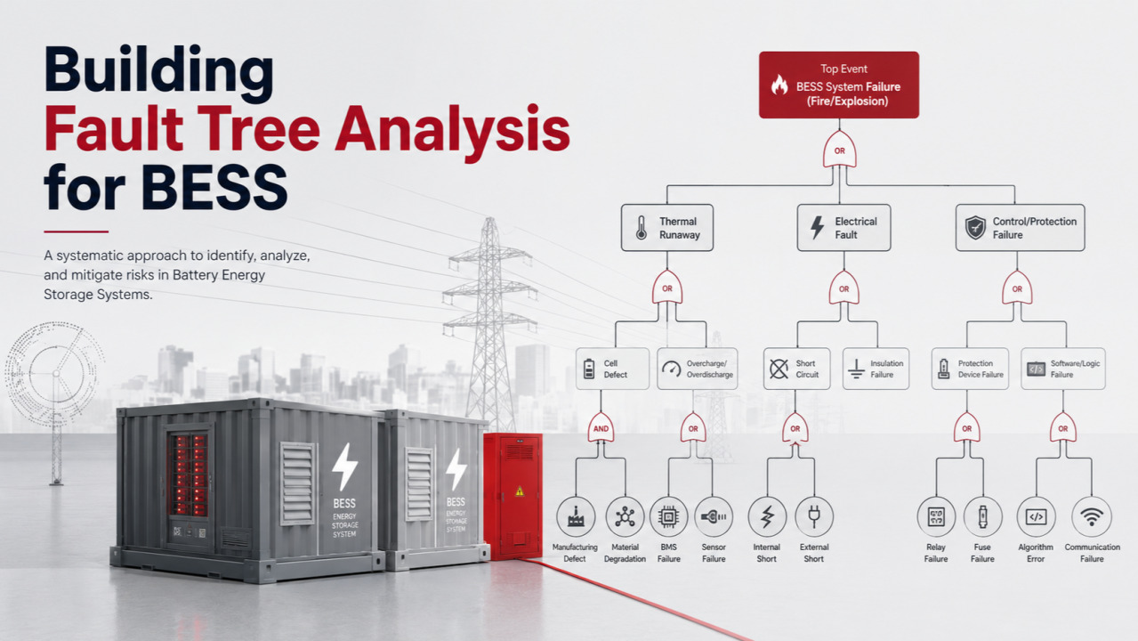
Battery Energy Storage Systems (BESS) are scaling rapidly across grid, C&I, and hybrid renewable applications, but this growth has been accompanied by a steady stream of fire and explosion incidents in containerized installations. Fault Tree Analysis (FTA) offers a structured, top-down engineering method to trace how combinations of component-level faults propagate into catastrophic system-level events such as thermal runaway, container fires, or deflagration. Unlike checklist-based safety audits, FTA uses Boolean logic gates (AND/OR) to map causal pathways from an undesired “top event” down to basic, quantifiable failure modes, enabling engineers, underwriters, and risk managers to calculate probabilities and identify the most critical failure combinations, known as minimal cut-sets.

FTA Methodology: Top-Down Logic Trees
FTA begins by defining a single top event — for a BESS, this is typically framed as “BESS fails to deliver required power” or “thermal runaway leading to fire/explosion”. Analysts then work backward, identifying the intermediate and basic events that could cause this outcome, connecting them through OR gates (where any single cause is sufficient) or AND gates (where multiple conditions must occur simultaneously). A widely cited practical framework organizes the top-level fault tree for BESS power delivery failure into five OR-gated branches:

AND-gate logic becomes essential for modeling compound hazard scenarios — for instance, a thermal runaway event escalating into a full container fire requires both cell-level thermal runaway AND a failure of the fire suppression or containment layer to intervene. This layered approach mirrors protection-layer modeling techniques used in process safety engineering, incorporating metrics like probability of failure on demand (PFDavg) for safety systems such as suppression and ventilation.
Core Building Blocks of a Fault Tree
A fault tree is built from a small set of standardized symbols representing events and logic gates. Understanding these is the prerequisite to constructing any BESS-specific tree.

Step-by-Step Process for Building a BESS Fault Tree
Step 1: Define the Top Event
Every fault tree analyzes exactly one top event, so the first design decision is scoping it precisely. For BESS, the three most common top events are thermal runaway propagation beyond the initiating cell, container/enclosure fire, and deflagration (explosion) of accumulated off-gas. Each deserves its own tree because the causal pathways differ substantially — a fire tree emphasizes ignition sources and suppression failure, while a deflagration tree emphasizes gas accumulation, ventilation performance, and ignition timing relative to gas buildup. Analysts with a broad understanding of the specific BESS design — cell chemistry, module and rack architecture, HVAC and ventilation layout, battery management system (BMS) architecture, and fire suppression design — are best positioned to define these top events accurately.

Step 2: Understand the System and Its Hazard Mechanisms
Before drawing logic gates, engineers need a detailed understanding of how the specific top event physically develops. For lithium-ion BESS, thermal runaway is a self-reinforcing process in which internal heat generation exceeds the system’s capacity to dissipate it, triggering electrolyte decomposition and the release of flammable and toxic gases such as hydrogen, carbon monoxide, methane, and ethylene. The NFPA 855 standard requires that flammable gas concentration in a BESS enclosure be kept below 25% of the Lower Flammability Limit through exhaust ventilation, which is why HVAC and gas-detection failures appear as recurring basic events in BESS fault trees. Recognized hazard categories under NFPA 855 and IEC 62933-5 include fire hazards, chemical release (corrosive electrolytes, toxic gas), physical impacts, and electrical hazards, and each category can seed its own branch of causal factors.

Step 3: Decompose the Top Event into Intermediate and Basic Events
Working top-down, the top event is broken into intermediate causes connected through logic gates, continuing until each branch terminates in basic events with a known or estimable failure rate. A representative top-level structure for a “BESS fails to supply required power” or “container fire” tree includes major OR-gated branches such as battery bank unavailability, power conversion system (PCS/inverter) failure, battery management system (BMS) failure or communications loss, auxiliary system failure (HVAC, DC bus), and grid/external protection trips.

Each branch decomposes further, for example:
- Battery bank unavailable: capacity loss below threshold from cell degradation/aging, thermal runaway leading to shutdown, string breaker/fuse opening, or high internal resistance from cell imbalance
- PCS/inverter failure: IGBT/semiconductor failure, control firmware crash, or DC/AC contactor stuck
- BMS failure: software/hardware crash or CAN/Ethernet communications loss to the PCS/EMS
- Auxiliary failure: HVAC failure leading to overtemperature trip, or loss of HV/auxiliary DC supply

Analogous logic applies to fire-specific trees; published white papers on BESS fault trees structure branches around thermal runaway initiation, container fire propagation, and deflagration, with basic-event libraries organized by cell, rack, container, and common-cause initiators such as a shared firmware defect across a battery string. AND gates are reserved for cases requiring simultaneous failure — for example, thermal runaway propagating to a fire requires both the runaway event AND failure of the fire-suppression system, since an intact suppression layer would otherwise arrest the escalation.
Step 4: Build the Basic Event Library
A rigorous BESS fault tree is only as good as its basic event library, which should be organized by hierarchical level — cell, module, rack, container, and site — plus a category of common-cause initiators that can defeat multiple protection layers simultaneously, such as a shared power supply fault or a single HVAC unit serving multiple racks.
Typical basic events drawn from BESS-specific literature include:

Wherever possible, basic event probabilities should come from documented sources rather than assumption: IEEE and Centre for Chemical Process Safety (CCPS) component failure-rate data, UL 9540A cell/module/unit-level propagation test results, manufacturer reliability data, and incident databases such as EPRI’s BESS Failure Incident Database provide the empirical failure rates and demand-based unavailability figures analysts need.

Step 5: Calculate Minimal Cut Sets and Top Event Probability
With gates and probabilities defined, the tree is solved algebraically or via software to extract minimal cut sets and compute the overall top-event frequency. In a published large-scale solar-plus-storage case study using a 13 MW site with a 5–10 MWh lithium-NMC BESS, the calculated frequency of worst-case total unit damage from a thermal-runaway fire fell in the range of roughly 2.4×10⁻⁶ to 2.8×10⁻⁵ occurrences per year, equivalent to about one worst-case event every 35,000 to 400,000 years, while the corresponding human-risk frequency from an unmitigated fire ranged from about 2.5×10⁻⁵ to 2.8×10⁻⁴ per year. That analysis also found that failure of either the fire-detection system or the active fire-suppression system was the critical path leading to unmitigated fire spread inside the BESS room, illustrating how minimal cut-set analysis pinpoints the specific safety-barrier failures that dominate overall risk.

Step 6: Validate, Interpret, and Feed Back into Design
The completed fault tree should be reviewed against known incident histories and, where possible, cross-checked with a complementary bottom-up method like FMEA (Failure Modes and Effects Analysis), which identifies component-level failure modes and computes Risk Priority Numbers (Severity × Occurrence × Detection) that can supply probability inputs back into the fault tree. This bidirectional relationship — FMEA feeding basic-event data into FTA, and FTA highlighting high-risk combinations that get added back into the FMEA — is a recommended practice for BESS reliability programs. Findings should translate into concrete design or operational changes: adding sensor redundancy, improving fire-detection coverage, hardening BMS firmware update processes, or introducing redundancy for auxiliary systems like pumps and HVAC fans that repeatedly appear as single points of failure.

Aligning the Fault Tree with Codes and Standards
Fault trees for BESS hazards are not built in isolation; they should be calibrated against NFPA 855 and IEC TS 62933-5, which define recognized hazard categories (fire, chemical release, physical impact, electrical) and prescribe safety-design requirements such as gas-concentration ventilation limits. UL 9540A testing — evaluated at cell, module, and unit levels — supplies empirical propagation and gas-generation data that can populate basic event probabilities directly rather than relying on generic component databases. Where large-scale fire or deflagration testing (e.g., CSA TS-800:24 large-scale fire tests, or NFPA 68/69 deflagration analysis) has been performed on a specific BESS unit, those results should supersede generic assumptions in the tree. Fire safety studies increasingly required by AHJs also draw on the EPRI BESS Failure Incident Database to validate that a fault tree’s basic event library reflects real-world failure modes rather than only theoretical ones.

Complementary and Alternative Methods
FTA is rarely used in isolation for BESS risk assessment, since a purely deductive top-down tree can miss dynamic, systemic, or organizational causes of accidents. Event Tree Analysis (ETA) takes the opposite, bottom-up approach: it starts from an initiating hazard release (such as thermal runaway or an external fire) and forecasts a sequence of possible outcomes based on whether successive safety barriers succeed or fail. Systems-Theoretic Process Analysis (STPA) is increasingly paired with FTA/ETA for BESS because it captures unsafe control actions arising from software, operator, and organizational interactions that purely component-failure-based fault trees can overlook, and integrated frameworks combining probabilistic event trees with STPA have been proposed specifically for large-scale solar-plus-storage safety assessment. More advanced quantitative research has also combined fault trees with Dynamic Bayesian Networks and Support Vector Regression to provide dynamic, real-time risk prediction for lithium-ion battery thermal runaway, moving beyond the static probability estimates of classical FTA.

Root Causes: What the Data Actually Shows
EPRI’s BESS Failure Incident Database, analyzing 26 classified incidents through 2024, challenges a common assumption: lithium-ion cells are rarely the primary root cause of failure. The biaxial classification splits root cause (design, manufacturing, integration/assembly/construction, or operation) from the failed element (cell/module, controls, or balance-of-system). The results show cells account for only about 11% of failures, while controls (46%) and balance-of-system components (43%) — including busbars, cabling, enclosures, HVAC, and fire suppression — dominate as failed elements.
Integration, Assembly & Construction was identified as the single most common root cause category, with the majority of these incidents traced to balance-of-system components such as DC/AC wiring, HVAC subsystems, and fire suppression hardware. Notably, some inspected BESS units were found to have defects in fire suppression systems, and 18% had thermal management system defects — both safety-critical subsystems within an FTA framework. Operational failures were also strongly linked to state-of-charge (SOC) mismanagement, with a significant fraction of incidents occurring when SOC exceeded 90% prior to the event.
Case Study: Victorian Big Battery Incident
The July 2021 fire at the Victorian Big Battery in Australia illustrates how an FTA would trace a real cascading failure. During commissioning of two Tesla Megapack units within a 212-unit site, a coolant leak in one unit’s liquid cooling system caused electrical arcing between battery modules, and the resulting heat triggered thermal runaway in that unit’s cells. While the unit’s insulated walls initially contained the fire from spreading laterally to an adjacent unit only 15 cm away, high winds carried flames from the roof to a neighboring unit, igniting combustible plastic roof components and allowing fire to reach the batteries below. Mapped onto a fault tree, this event required an AND-gate combination of cooling system failure, containment/barrier limitation, and an external environmental factor (wind) — precisely the kind of multi-causal pathway FTA is designed to surface and quantify.

A separate June 2023 incident in Warwick, New York, demonstrated a simpler OR-branch pathway: rainwater seepage into battery containers caused an electrical short and subsequent fire, tracing directly back to enclosure sealing as a basic event.
Protection Layers and Mitigation Mapping
Each FTA branch should map to a corresponding protection layer, since fault trees are most useful when paired with mitigation strategies rather than treated as a purely diagnostic exercise. The Battery Management System (BMS) functions as the first line of defense, monitoring cell-level voltage, current, and temperature in real time, blocking charging under unsafe conditions like low temperatures that risk lithium plating, and cutting off circuits when overcurrent is detected. The Power Conversion System (PCS) serves as an independent isolation layer, capable of rapidly de-energizing and disconnecting a faulted string or container to prevent it from feeding a fire or acting as an ignition source.

Physical protection layers add further redundancy: fire-resistant walls between modules slow fire spread, engineered deflagration (“blow-out”) panels relieve internal pressure safely during gas release events, and intumescent thermal barriers between cells or racks impede thermal runaway propagation. Notably, a large-scale Wärtsilä test conducted without active fire suppression demonstrated that a well-designed passive containment strategy — venting panels and fire-resistant barriers alone — could keep a thermal event contained, underscoring that FTA-driven design decisions about passive versus active protection layers carry real risk-reduction weight.

Cascading Hazards Beyond Fire
FTA for BESS must also branch into secondary hazard modes beyond direct fire propagation. Off-gassing produces flammable and toxic gases — including carbon monoxide, hydrogen, methane, and other hydrocarbons — that can reach their lower explosive limit and trigger a deflagration event if an ignition source is present, as occurred in a 2019 Surprise, Arizona incident. Stranded energy represents a distinct post-incident basic event: after a fire is extinguished, damaged battery terminals can leave an unknown quantity of electrical energy trapped in the cells, creating both a shock hazard for responders and a re-ignition risk that can materialize minutes to days after the initial event.

Quantitative and Probabilistic Extensions
Advanced FTA implementations increasingly incorporate fuzzy logic and dynamic probabilistic methods to address the sparse and uncertain failure-rate data available for BESS components. One 2024 study proposed a Fuzzy Fault Tree Analysis (FFTA) approach that combines expert knowledge aggregation with fuzzy logic to calculate probabilistic risk assessment metrics for lithium-ion BESS, feeding safety objectives into multi-objective system optimization alongside economic goals. A related methodology integrates fault trees with dynamic Bayesian networks and support vector regression to move beyond static probability estimates toward real-time, evolving risk prediction for thermal runaway as operating conditions change. These quantitative extensions matter directly for underwriting and insurance decisions, since FTA outputs such as top event frequency and minimal cut-sets can be used to explain “maximum foreseeable loss” scenarios to underwriters.

Practical Application: FMEA-FTA Integration
Industry practitioners increasingly pair FTA with Failure Modes and Effects Analysis (FMEA) in a complementary bottom-up/top-down workflow. FMEA works bottom-up, cataloging each component’s potential failure modes and effects, then scoring them by Severity, Occurrence, and Detection to compute a Risk Priority Number (RPN) that prioritizes corrective actions. FTA then uses this FMEA-derived basic event probability data as direct inputs to the fault tree, while conversely, high-risk combinations surfaced by FTA’s minimal cut-set analysis can be fed back into the FMEA to elevate previously underweighted component risks. This two-way integration is particularly relevant for BESS manufacturing and integration teams, since EPRI’s findings show that integration, assembly, and construction defects — not cell chemistry — are the leading root cause category requiring this kind of rigorous, cross-referenced risk modeling.
No responses yet